

프로젝트 설명
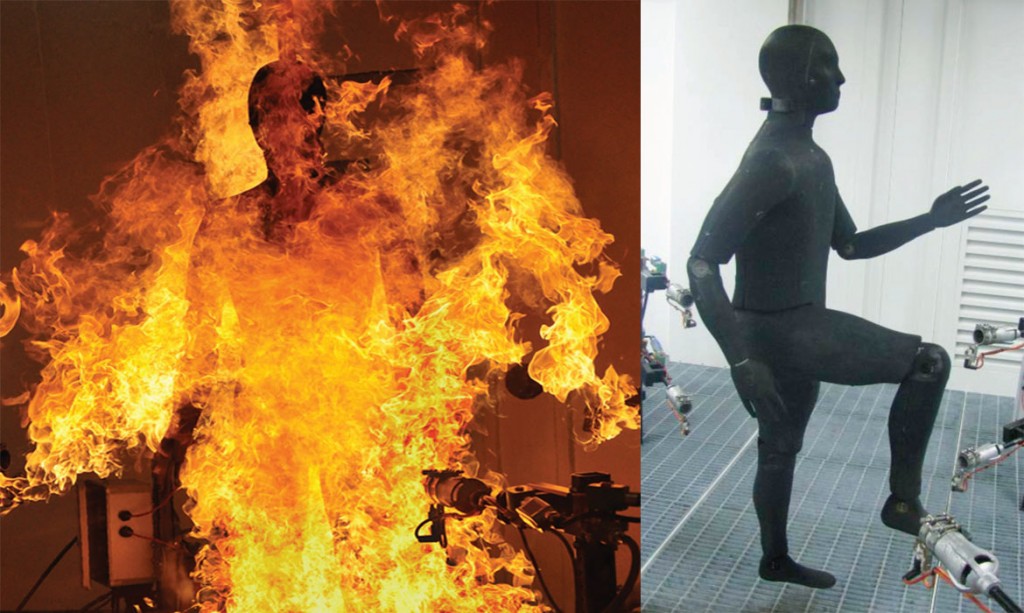
화염 전신 써멀마네킨(써멀마네킹)
Flame Test Thermal Manikin (Bernie Manikin)
화염 전신 써멀마네킨, 전신 마네킨
Flame Test Thermal Manikin, Full Body Manikin, Thermal Manikin
Product
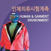
화염 써멀마네킨은 화재 현장 시뮬레이션을 통해 보호복 또는 의류등의 열 유속 및 보호 성능 등을 측정하기 위한 마네킨입니다.
이 시스템은 통합 센서, 완벽한 Turn-Key 시스템, 전자 제어, 이상적인 관절, 세라믹 복합체의 Body 형태를 갖추고 있습니다.
제품특징
- Newton Thermal Manikin을 기반으로한 고온 복합 신체 형태
- 서양 또는 동양의 일반 남성 신체 모형
- 열에 의한 손상을 보호하기 위해 모형 쉘에 통합
- 머리나 목 또는 상단을 통해 인체 모형에 필요한 케이블 연결
- 무선 통신 기능 가능
- 전용 PC 및 소프트웨어 포함
- 의류의 피팅이 용이하도록 각 관절 세분화
Features
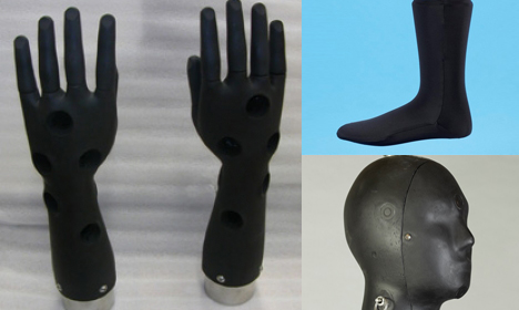
- Manikin shell is constructed from a ceramic composite material that is completely fireproof and will not degrade with use.
- Manikin joints feature adjustable settings to allow posing in fixed positions.
- Cable connections and manikin support can be configured through the top of the head, side or back of neck, or another alternate location per customer request.
- Data acquisition components are located within the manikin body to digitize signals near their source for highest accuracy measurements.
- Copper disc sensors do not degrade with use and provide a better match to human skin response.
- Hands disassemble for easy dressing and undressing of the manikin.
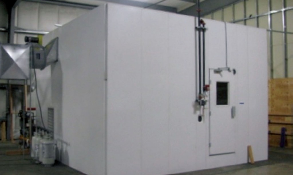
- Chamber includes gas distribution system and 8 or 12 torch array to apply a uniform flame front onto the manikin. Chambers feature a pre-engineered ventilation system to supply oxygen for combustion, and to vent the heated chamber space after a burn.
Specifications
Standard
• Flame Test Manikin meets the ASTM F1930 and ISO 13506 test standards.Body dimensions conform to ASTM D6240.
• Manikin construction utilizes a non-degrading, flame-proof ceramic-composite body form.
• Manikin jointed at the shoulders, elbows, hips, knees, and ankles. Mounting support and cable connection can be at the top of head, or side/back of neck to minimize penetrations in the test garment.
• 126 precision calorimeter heat sensors measure the incident heat flux over a range from 0.0 to 4.0 cal/cm2•s (167 kW/m2)
• A hand-held heat flux gun with NIST traceable reference sensor is provided for in-situ calibration of the manikin’s sensors
• Burn chamber ignition controls are integrated with the ventilation system to prevent buildup of explosive gases and quickly ventilate the chamber after a burn cycle is completed.
• Torch array is designed to provide a uniform heat flux of at least 2.0 cal/cm2•s (84 kW/m2)
• Redundant electronic and manual gas shutoff valves protect the system and operators, and the chamber is also equipped with approved fire suppression systems.
• Burn chamber includes mesh screens and activated charcoal filters to remove soot and any combustion byproducts/pollutants to ensure that local air quality is not affected.
• Chamber size is larger than the ASTM F1930 minimum dimensions to provide better combustion and ventilation, more uniform flame exposure, and sufficient space for safe movement around the manikin.
Site Requirements
The burn chamber design can be installed as a stand-alone exterior unit or installed inside an existing facility with the oversight and approval of local regulatory agencies.
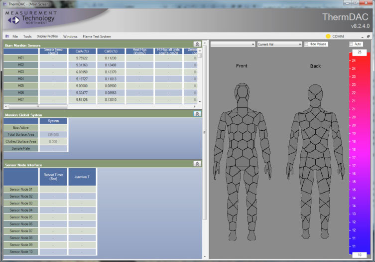
Therm DAC Control Software
ThermDAC Burn Model software incorporates data logging, real time statistics and data analysis, plus diagnostic and calibration functions. Software processes sensor data and calculates the degree and total area of predicted burn injury.